Thursday, September 23, 2010

Manual control of the high pressure pump.. is not a good practice?


While being in Delft, we were thinking that the more simplified the system the better would be. For this reason, we decided not to put any electronics or controllers to control the high pressure pump (Pearson pump).
However, after 4 days of full operation, it is obvious that the manual control of the pump is not the best practice.

The Pink line is the feed flow over time and the blue line is the irradiation over time, for two different days
The Pearson pump is powered by the PVs, which means that during the day, the pump has to be regulated manually depending on the fluctuations (clouds passing). Initially i thought that this wouldn't be very difficult, however because of the season's high sun fluctuations, its very difficult to  achieve the maximum flowrate for each instant irradiance. As a result, the operation of the motor is not optimised, and the total permeate production over the day is lower.

Maybe it would be a consideration to insert an automation system for the pearson pump, which will allow it to follow the fluctuations of the sun more accurately?

Wednesday, September 22, 2010

A Mobile Air-Conditioner for the Pearson Pump Motor - A Cool(ing) Solution!


Overheating of the Pearson Pump motor is a problem that we have faced since the beginning of our experimentation in Crete (the problem being aggravated due to lack of ventilation within the room that the facility has been placed in). Initially we had used a small table fan to supplement the cooling effect of the motor fan...

Table Fan Cooling System

However, it seemed that this didn't stop the motor of the Pearson pump from overheating. Prof. Diamandopoulos was kind enough to arrange a mobile air-conditioner unit (Cooling Effect = 2200W) for our system. It just arrived and I am very curious to see if indeed it makes a significant difference!

The Pearson Pump Motor with the Mobile Air-Conditioning Unit

Electrical Cables and New Voltage Sensor


Last week, while Andres was still in Chania, we noticed that it was difficult to keep changing between PV Power and Grid Power (in case we wanted to carry out some tests in the late afternoon when the PV Power was too low).


Basically, the two sources were equipped with different kinds of cables: the PV cables were bare, while the grid power cables had copper ring endings. 
We asked the electrician who had connected the PVs to help us find an easy solution for this and what he did was that he cut the copper ring endings off and put the bare cables in both the power sources. This week I learnt of a switch which can be installed between the two power sources and with easier way interchange between PV and grid power source. However, I need to speak to Sander (technician from TU Delft) about this to confirm that this will not lead to a loss in calibration.


An unfortunate incident which happened when the electrician was here is that in his effort to fix the cable he accidentally broke the sensor for the Voltage measurement. It took us two days to find where we can get supply of new resistors of the same type, and a tool to connect them. Consequently, for 2 days I was recording the voltage manually (on paper) after every 10 minutes.

My friend, Charalampos who studies Electronics here in the TUC helped me by making a new circuit.

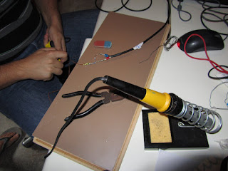
The Soldering-Iron with Charalampos
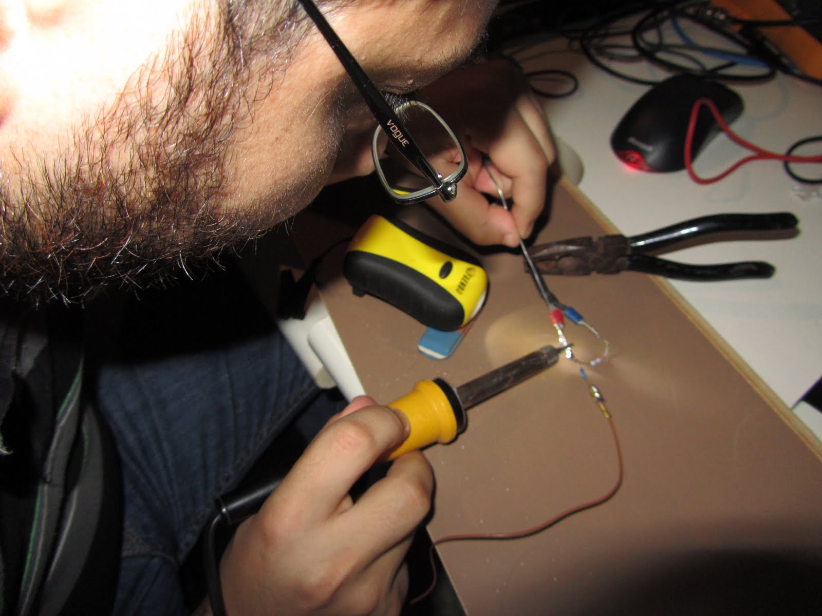
Charalampos in Action!

There is still a small deviation in the voltage readings we measure and those shown by the multimeter in the fusebox (coming from PVs). A Professor from the Electronics Engineering department is interested to see the facility and is coming tomorrow together with all the people from the laboratory. Hope they can give some good advice about it.