Last week i recorded a small video during operation of the system while the motor was operating smoothly. This gives a better impression of the whole installation and setting: the room, desk in the corridor, the system, tanks, piping, wiring, electrical and electronic setups, tools and devices, and airconditioning!
Tuesday, October 12, 2010
Monday, October 11, 2010
October shows early winter signs
October is almost midway but it already resembles very much of late november or even December. The weather is not at all typical of previous years when it was mostly sunny with high temperatures until late october.
Especially last week, the temperature was about 16-8 degrees Celcius and mostly cloudy, and with abrupt changes during the day which are very difficult to forecast. There were days that the system couldn't operate at all (like last weekend) because the irradiation never rose above 400 W/m2 when in order to start smooth operation, it needs at least 300 W/m2. In fact the maximum irradiation that was reached was half than the maximum of all the previous days in october and september:
Especially last week, the temperature was about 16-8 degrees Celcius and mostly cloudy, and with abrupt changes during the day which are very difficult to forecast. There were days that the system couldn't operate at all (like last weekend) because the irradiation never rose above 400 W/m2 when in order to start smooth operation, it needs at least 300 W/m2. In fact the maximum irradiation that was reached was half than the maximum of all the previous days in october and september:
 | |||
| Solar radiation day distribution on 09/10/10 |
 |
| Solar radiation day distribution on 10/10/2010 |
One typical day of the previous days in October was like on 8/10/10:
 |
| Solar radiation on 08/10/10 |
As it can be seen from the above graph, fluctuations in irradiation were significantly deep and abrupt. System operation without a motor speed regulator but manual control, was extremely difficult and inefficient while frequent start and stops to protect the pump were unavoidable.
All results have been logged with the datalogger and conclusions/comparisons will be announced later this week.
Wednesday, October 6, 2010
Observations from the system operation with LCB and without!
The LCB controller or Linear Current booster is used in solar direct pumping applications. It is claimed to achieve 30 - 90 % increase in the water pumped than connecting the motor directly to the solar panels. At times when the sun is not optimum, a Linear Current Booster boosts the current in the pump motor to produce the torque to turn the pump motor. It does this by sacrificing voltage on motor, hence the motor runs slower. This results in a motor that may be pumping slower (there is after all less solar power), but this is better than having a stalled pump pumping nothing which would happen if solar direct.
The LCB that we are using is from the company "Solar Converters Inc".
So, what are the things which have been observed so far?
Observations from the absence of the LCB:
In the last week of September (when LCB was not still connected), the sky was heavily clouded (leading to a (global) irradiation of <200 W/m2 for most time of the day for 4 days) and system operation was difficult. The motor was abruptly stalling, leading to significant vibrations and the motor starting and stopping almost every 10 minutes. However, that practice is not safe for the motor over extended time scales, and neither does it producing good results from which conclusions can be drawn. The situation is aggravated by the absence of a speed controller for the Pearson pump, the need for which is felt especially in times when there are wide fluctuations in the irradiation levels.
Observations with the use of the LCB:
On 3/10/2010, 5 days of system operation with LCB were completed.
 |
The LCB controller mounted on the wall |
 |
| Open without the cover |
 |
| The PCB of the controller with the LEDs flashing indicating the voltage levels |
 |
| Opening at the cover case in order to observe the LEDs with the cover on |
Experimentation trials:
29/09/2010: First trial with LCB at 13:00
30/09/2010: Full day of experimentation (2nd trial)
01/10/2010: Half day of experimentation. Campus-wide power failure of 3 hours resulted in stoppage of operation and destruction of data from the data logger.
2/10/2010: operation during first half of the day. Heavy clouds were observed after 14:00 until sunset.
3/10/2010: operation during second half of the day due to dark sky.
After connection and operation with the LCB, the following were observed:
- Motor doesn’t stall and noise is smoothened.
- Solar fluctuations smoothened by the LCB. The controller avoids deep and steep changes of motor speed.
- By observing the LCB LEDs which measure the Voltage level supplied every moment, it is easy to predict when the motor speed has to be adjusted (in clear sky conditions).
- Significant Exchange of Voltage with Current occurs most of the time, in order to supply with the maximum instant current possible. However, the limitation of the LCB is 40 A and it cannot give more than that. Luckily, the flow rate corresponding to this limitation coincides with the recommended limit of the membranes for feed flow set by manufacturer at a maximum of 6gpm (gallons per minute). After 5 days experimentation, it was observed that the 40 A were corresponding to feed flow of 6 gpm or higher. As a result, the limitation of the 40A doesn’t effectively limit the system’s capacity.
- The system operates with higher power than before the LCB during low irradiation in the morning and especially in the afternoon.
- Voltage Exchange for one specific irradiance value depends on the type of the irradiation (if it is direct or diffused). In direct irradiation the LCB manages to give more current than when the same amount if irradiation is diffused. For example, in the afternoon the LCB can give more current (corresponding to higher permeate flow) than in the morning, for the same irradiation. It is important to note here that this is attributed to the characteristics of the PV panels.
- LCB works better when there are no rapid fluctuations. When irradiation reduces smoothly, then the voltage levels also reduce smoothly (due to LCB), and current increases considerably.
Thursday, September 30, 2010
Electrical switch and LCB get installed
Simplifications of systems sometime cause a lot of inconvenience and insecurity. This was the case also to our system which in the beginning had as simple electrical connections as possible:
any time there was a need to change the power source, a procedure of at least 10 min had to be followed with a lot of screwing and unscrewing in fuses, raw cable manipulation, and tapes..
Luckily this was solved this week, with some great family help, a switch got installed between the PVs and the rectifier. We also installed the LCB between the PVs and the switch as well as some extra fuses before the motor as suggested by the LCB manufacturer:
 | |
| Electrical connections diagram |
Some photos of this amateur installation:
 |
| Putting a wood plate as a base in order to avoid drilling too many holes on the wall |
 |
| The switch |
 |
| Installing the switch |
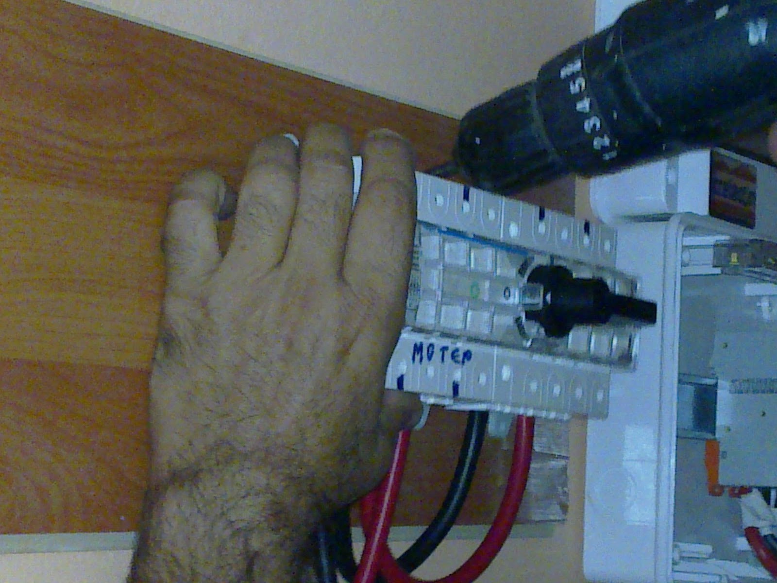
 |
| The switch between the LCB and the fusebox |
Monday, September 27, 2010
One interesting visit from the stuff of the Laboratory of Electric Circuits and Renewable Energy Sources from the Electronic Engineering Department
Last week the Laboratory of Electric Circuits and Renewable Energy Sources from the Electronic Engineering department visited our installation, together with the professor dr.Kalaitzakis and 5 master students (http://www.ece.tuc.gr/
They were very interested in our project, since they are also involved in desalination (of course from the power and control systems point of view) and we discussed many topics like the introduction of the automatic controller so that I free my hands and also get more accurate results. Furthermore, they expressed their worries about the motor lifespan under such fluctuating operations. They are afraid that it won't last for long without damages and that we should take care for its protection. They suggested to install a supercapacitor (small), which will only serve purposes of smoothing these deep current fluctuations in order to provide stable current to the motor.
The LCB may help the situation with the fluctuations but for sure it will not replace the manual regulation of the motor speed by me during day operation.
We also discussed about the Voltage and current losses which i observe in datalogger and they think that they are remarkable. However, it is not very obvious what is the reason, it may be the sensors construction or some resistance occuring via the connections.
Another suggestion was to introduce a W-meter at the PV panels, so that i know also the power from the PV panels and estimate better how much losses i get while measuring with the datalogger and account for them.
Kostas and Ariadni, master students at the Laboratory, visited again the installation trying to understand better how the motor works and find out the safe operating range. After contact with Spectra (the provider of our system), we were informed that there is no operating range as such and no minimum voltage requirement. Ariadni and Kostas found this strange, since all motors have an operating range in which they operate constant and safe.
Maybe this has to do with this specific motor which is permanent magnet dc current?
this is something still to answer..
Thursday, September 23, 2010
Manual control of the high pressure pump.. is not a good practice?
While being in Delft, we were thinking that the more simplified the system the better would be. For this reason, we decided not to put any electronics or controllers to control the high pressure pump (Pearson pump).
However, after 4 days of full operation, it is obvious that the manual control of the pump is not the best practice.

 |
| The Pink line is the feed flow over time and the blue line is the irradiation over time, for two different days |
Maybe it would be a consideration to insert an automation system for the pearson pump, which will allow it to follow the fluctuations of the sun more accurately?
Wednesday, September 22, 2010
A Mobile Air-Conditioner for the Pearson Pump Motor - A Cool(ing) Solution!
Overheating of the Pearson Pump motor is a problem that we have faced since the beginning of our experimentation in Crete (the problem being aggravated due to lack of ventilation within the room that the facility has been placed in). Initially we had used a small table fan to supplement the cooling effect of the motor fan...
 |
| Table Fan Cooling System |
However, it seemed that this didn't stop the motor of the Pearson pump from overheating. Prof. Diamandopoulos was kind enough to arrange a mobile air-conditioner unit (Cooling Effect = 2200W) for our system. It just arrived and I am very curious to see if indeed it makes a significant difference!
 |
| The Pearson Pump Motor with the Mobile Air-Conditioning Unit |
Electrical Cables and New Voltage Sensor
Last week, while Andres was still in Chania, we noticed that it was difficult to keep changing between PV Power and Grid Power (in case we wanted to carry out some tests in the late afternoon when the PV Power was too low).
Basically, the two sources were equipped with different kinds of cables: the PV cables were bare, while the grid power cables had copper ring endings.
Basically, the two sources were equipped with different kinds of cables: the PV cables were bare, while the grid power cables had copper ring endings.
We asked the electrician who had connected the PVs to help us find an easy solution for this and what he did was that he cut the copper ring endings off and put the bare cables in both the power sources. This week I learnt of a switch which can be installed between the two power sources and with easier way interchange between PV and grid power source. However, I need to speak to Sander (technician from TU Delft) about this to confirm that this will not lead to a loss in calibration.
An unfortunate incident which happened when the electrician was here is that in his effort to fix the cable he accidentally broke the sensor for the Voltage measurement. It took us two days to find where we can get supply of new resistors of the same type, and a tool to connect them. Consequently, for 2 days I was recording the voltage manually (on paper) after every 10 minutes.
My friend, Charalampos who studies Electronics here in the TUC helped me by making a new circuit.
 |
| The Soldering-Iron with Charalampos |
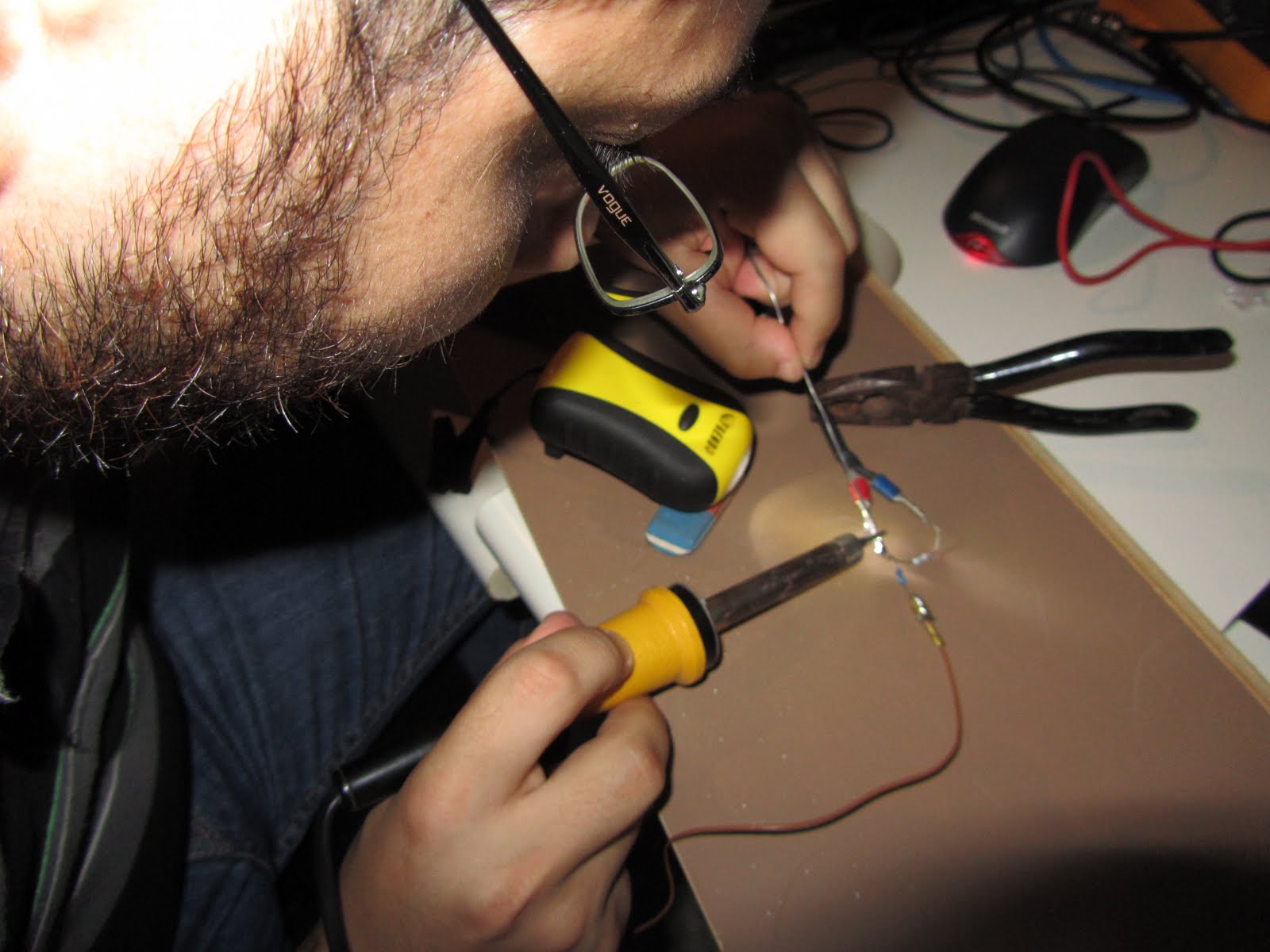 |
| Charalampos in Action! |
There is still a small deviation in the voltage readings we measure and those shown by the multimeter in the fusebox (coming from PVs). A Professor from the Electronics Engineering department is interested to see the facility and is coming tomorrow together with all the people from the laboratory. Hope they can give some good advice about it.
Subscribe to:
Posts (Atom)